This article documents my learnings from designing and building a DIY Pen Plotter during the summer of 2023. My ultimate goal is to build my own CNC machine, and a pen-plotter seemed like a good stepping stone towards this project — this is an important context for how I designed this machine, as if I only wanted a pen-plotter, a lot of things could be simplified.

My hope is that this collection of notes will be useful to you if you ever embark on a similar project:
Up to this point, all my designs for 3D-printed objects were either made in code (using my own tools, of course: Modeler and hiccup-sdf) or using SolveSpace.
The code-based approach is great for parametric designs or art projects (like FabFungus), while SolveSpace is awesome for quick sketches. In this project I had to figure out how to combine multiple parts together, and there was just no way around trying a serious tool — I went with Fusion 360 just because I had heard about it previously.
You can easily find a ton of "get started with" tutorials for Fusion 360 on YouTube — I can't point to one that was the most helpful. I just watched a couple of them and started playing around with the tool (which is free for personal use).
When designing 3D-printed parts to connect real-life objects, you'll want to reference these objects in CAD.
You can model them yourself, but usually it's possible to find them in the GrabCAD Library.
For Fusion 360 you want .stp files, which you can add to your project.
Here's a tutorial from Autodesk.
3D-printed objects tend to shrink after they are printed. Nothing in reality fits as perfectly as what you design in CAD. If you make an exact 20mm by 20mm hole for an aluminum profile, there's a big chance that it just won't fit after the print. What I did, was print a couple of draft versions of the part with various sizing adjustments to test what fits exactly right, and then used that throughout the design. For example, in my setup, this meant printing 3.2mm instead of 3mm holes for M3 screws, 8.4mm instead of 8mm for the rotating trapezoidal screw, etc.
For Fusion 360 itself, I recommend adjusting two settings:
- Turning on native trackpad support for a better trackpad experience.
- Disabling graphic effects for much better performance.
As for the design itself, I wouldn't recommend going for wheels for the Y-axis, as you can see in the picture above. It's very hard to get the tolerances just right, and my Z-axis is very wobbly. This is fine for a pen-plotter, but a no-go for CNC. I'm planning on redesigning this to use two linear rods with linear bearings, which should create a much more rigid structure than the one I have for the Z-axis.
The way most DIY 3D-printers, pen-plotters, and CNC's are built is by combining widely available prefabricates with 3D-printed objects.
I designed the body of my pen-plotter using:
- 20x20mm aluminum extrusions (often called just
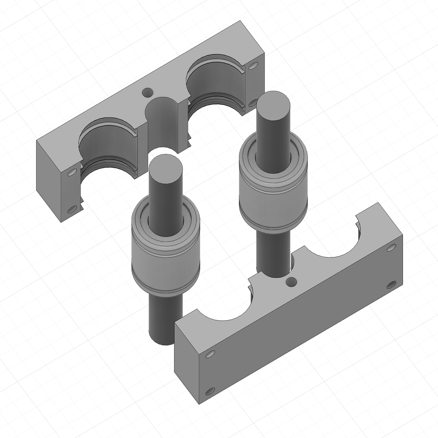
2020) - 10mm linear rods and matching 10mm linear bearings (
LM10UU) - 8mm ACME lead screws with matching lead screw nuts
NEMA17-clones for motors- aluminum couplings for connecting the motors with the lead screws
Another option for transforming the motor's rotation into linear motion is by using belts, but I decided that the lead screws would be better for the CNC, as intuitively, it feels like more force can be transferred this way. Also, I don't have to worry about tightening the belts.
For getting these parts, 3D-printer shops are your best bet. Motors can get quite expensive, and I just went with the cheapest ones I could find. The aluminum extrusions, rods and lead screws you can get cut to size (or cut on your own if you have the proper tools), but I managed to just find ones that fit my build (and sometimes I designed around what I could find).
For connecting the extrusions to 3D-printed parts, I used the standard approach of adding T-nuts in the profiles, leaving holes in the design where the T-nut should be, and screwing them together. If you've ever assembled a 3D-printer, you know what I'm talking about, if not, just search YouTube for T-nuts, I guess.

The linear bearings are sandwiched between two 3D-printed parts that I screw together. This was the part of the design that I had to do the most trial-and-error to fit perfectly.
To move the motors, you'll need a couple of electronic parts. I went with what seems to be a standard setup:
- Arduino CNC Shield
- four
A4988motor drivers - cheap Arduino UNO clone I had in my drawer
- a power supply — I had a 3A 12V one in my drawer too, and it seems to do just fine
- end-stops — anything that you'll find in your electronic store of choice should be just fine, I went with the cheapest mechanical ones I could find (two per axis, so six in total)
You'll want to set up VRef for your motor drivers — again, there are a ton of tutorials about that on YouTube.
This is mainly so the motors don't overheat.
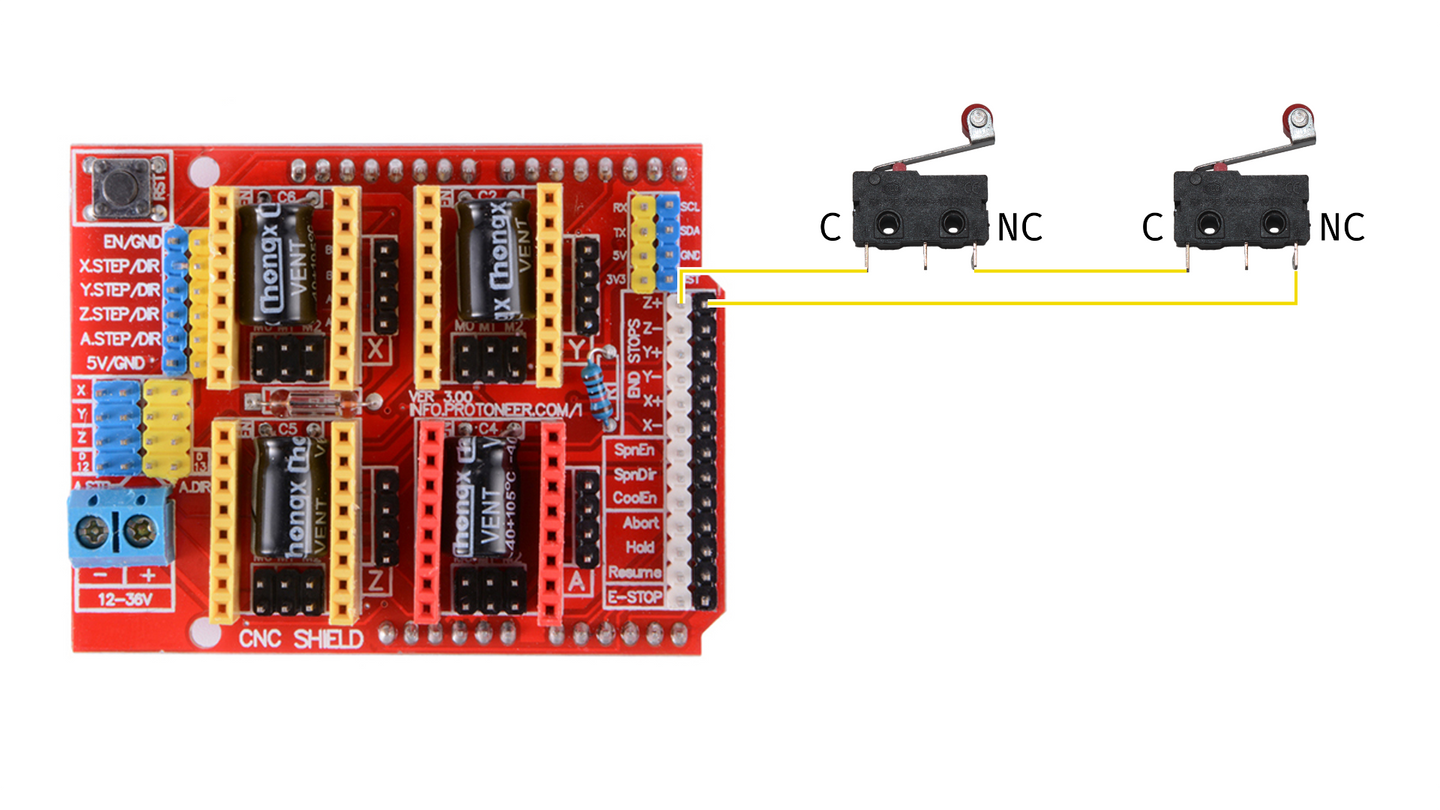
End-stops are a safety feature, so the machine gets a "hard stop" when it physically hits a certain limit (instead of destroying itself). They can be "normally opened" (NO) or "normally closed" (NC). I went with "normally closed", as they are safer — if a wire connection breaks for whatever reason, the result will be the same as if the end-stop was triggered. With "normally opened" ones, we don't get that safety.
Properly wiring two "normally closed" end-stops per axis wasn't immediately obvious to me, especially going through the CNC Shield. What seems to work is wiring them in sequence, connecting one end to the axis end-stop pin and the other to the ground, like so:

To debug the motors and end-switches wiring with the CNC Shield, it's best to use simple ad-hoc Arduino code instead of going for a full GRBL install, as it introduces another layer of indirection and makes it harder to pinpoint where the issue might be coming from.
Below is the code I used to see if I could move one motor.
To test different motors, adjust the dirPin and stepPin which you can find by looking for the CNC Shield pinout.
#define dirPin 5
#define stepPin 2
#define enablePin 8

// adjust these based on the motor spec
#define stepsPerRevolution 200
#define microsPulseWidth 250
#define microsBetweenSteps 1000

void setup() {
  pinMode(stepPin, OUTPUT);
  pinMode(dirPin, OUTPUT);
  pinMode(enablePin, OUTPUT);
  digitalWrite(enablePin, LOW);
}

void stepMotor() {
  digitalWrite(stepPin, HIGH);
  delayMicroseconds(microsPulseWidth);
  digitalWrite(stepPin, LOW);
  delayMicroseconds(microsBetweenSteps);
}

void loop() {
  // rotate clockwise
  digitalWrite(dirPin, HIGH);
  for (int i = 0; i < 5 * stepsPerRevolution; i++) {
    stepMotor();
  }

  delay(1000);

  // rotate counterclockwise
  digitalWrite(dirPin, LOW);
  for (int i = 0; i < 5 * stepsPerRevolution; i++) {
    stepMotor();
  }

  delay(1000);
}
And here's what I used to debug the end-stops:
#define xLimitPin 9
#define yLimitPin 10
#define zLimitPin 11

void setup() {
  Serial.begin(115200);
  pinMode(xLimitPin, INPUT_PULLUP);
  pinMode(yLimitPin, INPUT_PULLUP);
  pinMode(zLimitPin, INPUT_PULLUP);
}

void loop() {
  Serial.print("x = ");
  Serial.print(digitalRead(xLimitPin));
  Serial.print("y = ");
  Serial.print(digitalRead(yLimitPin));
  Serial.print("z = ");
  Serial.println(digitalRead(zLimitPin));

  delay(200);
}Once all the axes move and the end-stops are wired properly, it's time to start controlling the machine with G-code, the standard for 3D-printers and CNC machines.
Luckily, there's an open-source G-code interpreter for Arduino UNO and the CNC Shield called grbl.
The installation is pretty straight-forward, and described here — you basically add grbl as an Arduino library and then upload the only sketch that it provides: GrblUpload.
There's one adjustment I had to make in config.h, the configuration for the controller — I commented out #define VARIABLE_SPINDLE which conflicts with Z-axis end-stops.
Once grbl is running on the Arduino, the real fun starts — configuring all of its settings.
You can do this directly through the Arduino serial console, but I decided to switch to a GUI, so it's easier to test and control the machine.
I went with cncjs, after testing a couple of other apps that didn't seem to work correctly for whatever reason.
For the configuration, there's a lengthy documentation on the grbl wiki; here are the things that I did:
- calculated steps per mm for the motor movement, as described here
- adjusted maximum rate for the motor's, as described here
- inverted some of the motors axes to move in a predictable way
- enabled end-stops:
- finally, I homed the machine (using the button in the GUI), and stepped it manually to the other end-stop to figure out the soft limits (which also have to be enabled)
To plot anything, the machine needs G-code describing the sequence of motor moves.
There are many ways of generating it, the one I went with was vpype and vpype-gcode — a powerful command-line tool for everything SVG and plotters.
Since this is a completely custom pen-plotter, I had to create my own configuration for vpype-gcode, which looks like this:
[gwrite.plotter]

document_start = '''
G90       ; absolute coordinates
G21       ; mm units
G17       ; xy plane
G00 Z-15  ; pen up
'''

segment_first = '''
G00 Z-20  ; pen down
G00 X{x:.4f} Y{y:.4f}
'''
segment = '''
G00 X{x:.4f} Y{y:.4f}
'''
segment_last = '''
G00 X{x:.4f} Y{y:.4f}
G00 Z-15  ; pen up
'''

document_end = '''
M2        ; program end
'''

unit = "mm"

# scale is (1 / (1/96 inch to mm))
# making 1px in SVG == 1mm in real world
scale_x = 3.779527559
scale_y = 3.779527559
This configuration scales the resulting G-code so 1px in SVG equals 1mm.
To plot an SVG file I first convert it to G-code:
vpype --config vpype-config.toml read image.svg gwrite -p plotter image.gcodeThen I start the machine, home it ($H command into grbl), and manually jog the X/Y axis if I want to start the drawing somewhere else rather than in the lower-left corner.
Finally I zero-out the axes to where they are G10 L20 P1 X0 Y0 Z0 (so the 0/0/0 is where the tool is), and I'm ready to load up the resulting image.gcode and hit "run".
Anatomy of a CNC Router covers materials and software in way more detail than I did here. PrintNC is the recommended route if you want a DIY project, but not one made completely from scratch.
I collected some learnings and resources from the process here: Building a DIY Pen Plotter.